The Impact of Debris Shields on Laser Focusing
- Article Content:
Introduction
Laser technology has revolutionized various industries, from manufacturing to medicine, by providing precise and powerful tools for cutting, welding, and even medical procedures. The success of these applications heavily relies on the precision and focus of the laser beam. However, maintaining optimal focus can be challenging due to the presence of debris and contaminants that can interfere with the laser's performance.
This is where debris shields come into play. Debris shields are protective barriers designed to prevent debris from reaching the laser optics, ensuring that the laser beam remains clean and focused. In this white paper, we will explore the crucial connection between debris shields and laser focus, highlighting their importance in enhancing laser performance and efficiency.
Understanding Debris Shields
Debris shields are transparent barriers placed in the path of the laser beam to prevent particles, dust, and other contaminants from reaching the laser optics. Their primary purpose is to maintain the quality and precision of the laser beam by keeping the optical components free from debris.
The materials used for debris shields are carefully selected to ensure they can withstand the intense conditions of laser operations. Common materials include high-quality optical glass such as fused silica, sapphire and ZnSe to name a few. Design considerations for debris shields include factors such as:
- Transparency: The shield must be highly transparent to allow the laser beam to pass through without significant loss of power.
- Durability: The shield must be able to withstand the high temperatures and intense light of the laser without degrading.
The debris shield should be easy to replace when it becomes contaminated or damaged, ensuring minimal downtime for the laser system.
Impact on Laser Focus
The presence of debris shields directly impacts the focus of the laser beam. A clean and focused laser beam is essential for achieving high precision in various applications, such as cutting, welding, and medical procedures. Debris shields help achieve this by preventing contaminants from distorting the laser beam, allowing it to maintain its focus and deliver consistent performance.
When a debris shield is placed after a focusing lens, it will alter where the laser beam focuses. When light passes through a debris shield, it bends (refracts) at both the input and output surfaces of the shield. This bending causes the focus of the laser beam to shift. The amount of shift depends on the thickness of the debris shield and its material properties.
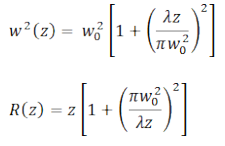
When light converges through a plane, parallel plate in air, the resulting refraction will extend the focus by the following relationship1:

( 1 )
Where is the index of refraction of the plate and is the thickness of the plate and and are the entrance angle of the ray and refracted angle of the ray. For a paraxial† ray, the equation can be simplified to:

( 2 )
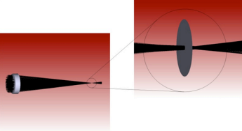
Figure 1 is a graphic representation of the displacement of the focused laser beam.

Figure 1: Lens focusing through a fused silica plate
If we zoom into either the upper or lower rays as they pass through the glass plate, we can see the refraction that occurs which causes the displacement of the focus position. Figure 2 shows how the ray refracts through the glass plate as it enters at the angle . At the glass to air interface, the lower ray (dashed line) is the original direction of the light from the lens as it would pass through air and the upper ray which is the refracted beam through the glass at the angle . It is this refraction which causes the focus to extend beyond the original position in air.

Figure 2: Zoom at the upper ray as it refracts through the glass plate.
Let’s look at an example and evaluate the focal shift a debris shield will induce. For this evaluation we will be introducing a 3 mm thick fused silica debris shield into a 1070 nm fiber laser system. The index of refraction of fused silica at 1070 nm is 1.449561.
Using equation ( 2 ), we can expect to get a focal shift of 0.93 mm. This means that the focusing lens will have to be repositioned 0.93 mm away from the intended focal plane.
Depending upon how critical the focal position is, the thickness tolerance of the debris shield can also have a significant impact on the focus position. A common thickness tolerance for a glass window is +/- 200 microns. Given the example above, how much will the focal position very with a debris shield that is 3 mm (+/- 0.2 mm) thick?
The minimum thickness of the debris shield would be 2.8 mm and a maximum thickness of 3.2 mm. Using the equation ( 2 ) above, we get a minimum focus shift of 0.87 mm and a maximum shift of 0.99 mm. Therefore, replacing a debris shield can cause the nominal focus position to shift ~ +/- 62 microns.
Advantages of Using Debris Shields
- Enhanced laser performance and efficiency: This ensures that the laser beam remains clean and focused, leading to improved performance and efficiency in various applications such as cutting, welding, and medical procedures.
- Protection of laser components from damage: By preventing particles, dust, and other contaminants from reaching the laser optics, debris shields protect the laser components from potential damage. This helps in extending the lifespan of the laser system and reducing the need for frequent maintenance
- Cost-effectiveness and longevity of laser systems: The use of debris shields can lead to significant cost savings in the long run. By protecting the laser components and maintaining optimal performance, debris shields contribute to the longevity of the laser system, reducing the need for costly repairs and replacements.
Challenges and Considerations
- Potential drawbacks or limitations of debris shields: One of the main challenges is that debris shields can sometimes introduce optical distortions or reflections that may affect the quality of the laser beam. This can lead to a reduction in the precision and accuracy of the laser's performance.
- Maintenance and replacement of debris shields: Debris shields require regular maintenance and replacement to ensure they remain effective. Over time, debris shields can become contaminated or damaged, which can impact their ability to protect the laser optics. Ensuring minimal downtime for the laser system during maintenance and replacement is crucial.
- Material Selection and Design: The materials used for debris shields must be carefully selected to withstand the intense conditions of laser operations. Factors such as transparency, durability, and ease of replacement are important to consider in the design of debris shields.
- Impact on Laser Focus: The presence of debris shields can influence the focus of the laser beam. The placement and thickness of the debris shield can affect the position of the laser's focus, which needs to be carefully managed to maintain optimal performance. In addition, thermal lensing can occur due to the type of glass used and how dirty the debris shield becomes.
- Future advancements in debris shield technology: Ongoing research and development in debris shield technology aims to address these challenges by improving the materials and design of debris shields. Innovations in this field can lead to more effective and efficient debris shields that enhance the performance and longevity of laser systems.
Conclusion
Debris shields play an essential role in maintaining the precision and efficiency of laser systems across various applications. By preventing contaminants from reaching the laser optics, debris shields ensure that the laser beam remains clean and focused, which is essential for achieving high precision in cutting, welding, medical procedures, and scientific research. The use of debris shields not only enhances laser performance but also protects the laser components from potential damage, contributing to the longevity and cost-effectiveness of laser systems.
However, the implementation of debris shields comes with its own set of challenges and considerations. Optical distortions, maintenance requirements, material selection, and the impact on laser focus are critical factors that need to be carefully managed to optimize the performance of debris shields. Ongoing research and advancements in debris shield technology aims to address these challenges, leading to more effective and efficient solutions that will further enhance the capabilities of laser systems.
In conclusion, debris shields are indispensable components in laser systems, providing essential protection and maintaining optimal performance. As technology continues to evolve, the development of advanced debris shields will play a crucial role in the future of laser applications, ensuring precision, efficiency, and longevity in various industries.
† Paraxial is an adjective used in physics to describe a light ray that is parallel to the axis of an optical system. It is also used to describe the space in the immediate neighborhood of the optical axis of a lens or mirror.
- Article Picture:
- Last Updated Date: 2025-03-28
- Hits: 1137